Extrude 2D Texture in 3D
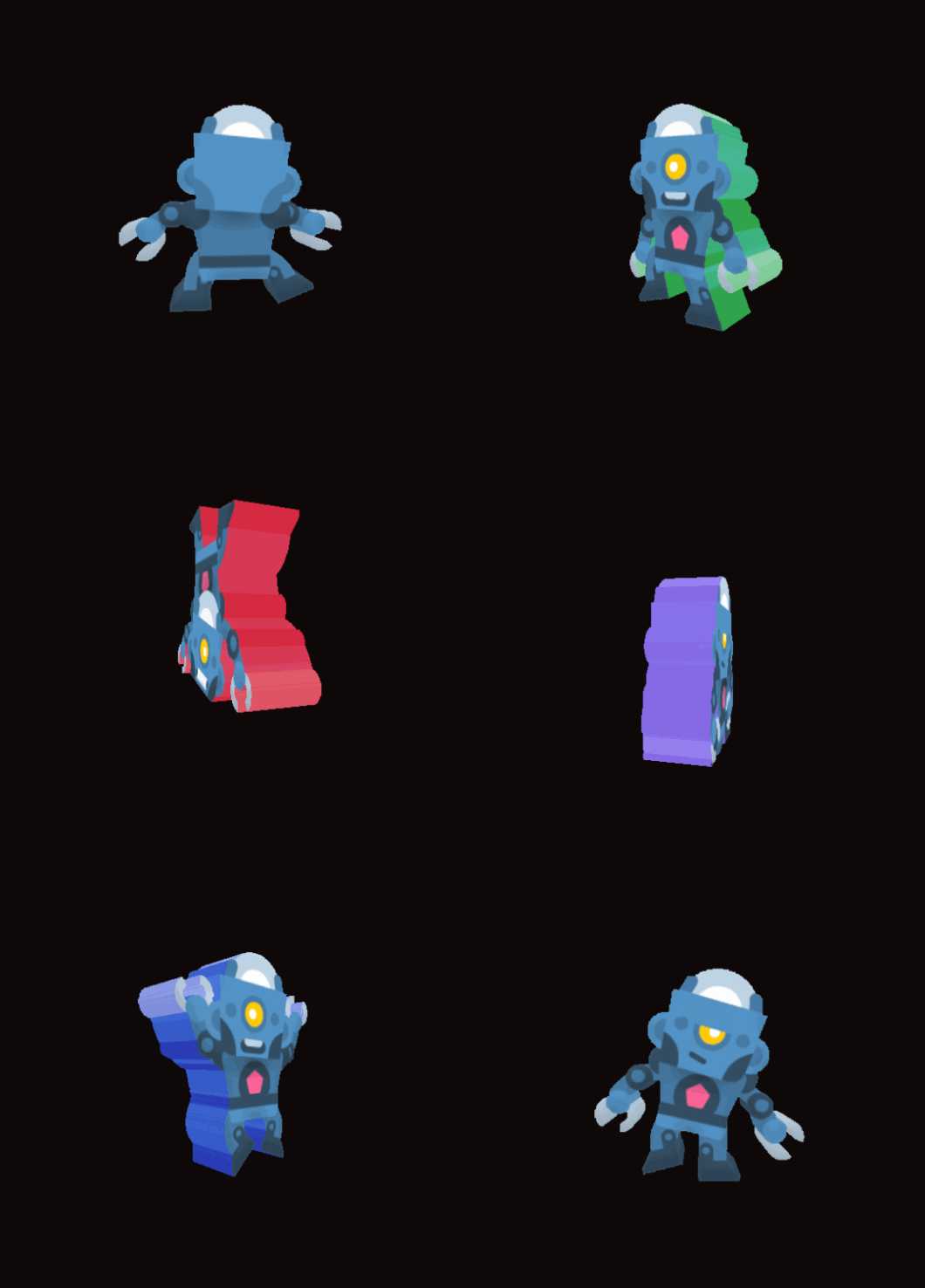
Add thickness to your 2D sprites!
Instructions:
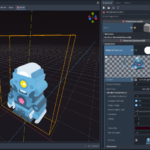
- Create a new MeshInstance3D in your 3D scene
- Add a Boxmesh to the instance (Shader only works with cubes)
- Add the shader to your Material
- Add an image with transparency
- Fine tune final result with extra parameters
- Sublime!
Note: If image resolution is very low use filter_nearest_mipmap with the Texture import so result is not blurry
Robot from Toon Characters 1 · Kenney
Shader code
shader_type spatial;
render_mode unshaded, depth_prepass_alpha;

// Will ignore pixels with alpha below this value for extrusion
uniform float extruded_alpha_cull : hint_range(0.0, 1.0) = 1.0;
// If pixels with alpha are extruded, this sets the alpha to 1
uniform bool opaque_extrude = true;
// Keeps original image on front and back of cube unaffected by other parameters
uniform bool keep_image = true;
// Same as above but for original image
uniform float image_alpha_cull : hint_range(0.0, 1.0) = 1.0;
// Offset extruded portion
uniform vec2 offset = vec2(0.0);
// Change color of extruded portion
uniform vec4 color_mix : source_color;
// 0 is no mix, 1 is solid color
uniform float mix_strength : hint_range(0.0, 1.0) = 1.0;
// 2D image where opaque pixels are extruded
uniform sampler2D Texture : source_color, filter_nearest_mipmap;
// Line is drawn to find colored pixel, below number puts that amount of points along line to check for collision
// In other words, maximum amount of texture() calls, too many texture() calls will cause lag
// Lower numbers will not extrude colors correctly, but that's fine if you plan to replace the color
// Too low and thin sections of image will not be extruded
uniform int texture_calls = 20;
// Shifts ray intersection checks, can increase thickness at low texture calls
uniform float ray_bias = 1;
// Allow hollow regions in texture to extrude forever
// Turning this on reduces number of texture calls needed for a full extrude significantly
uniform bool infinite_holes = false;
// Parameters to change if your texture is a spritesheet
uniform int Hframes = 1;
uniform int Vframes = 1;
uniform int frame = 0;

struct imgPoint {
	vec4 color;
	vec2 uv;
};

bool isInImg(vec2 uv){
	return 	uv.x >= 0.0 && uv.y >= 0.0 && uv.x <= 1.0 && uv.y <= 1.0;
}

vec2 getPositionAlongTheLine(vec2 a, vec2 b, float percentage) {
    return vec2(a.x * (1.0 - percentage) + b.x * percentage, a.y * (1.0 - percentage) + b.y * percentage);
}

vec2 lineImgIntersect(vec2 x, vec2 y){
	float t = 0.0;
	float xY = y.x;
	float yY = -y.y;
	float xX = x.x;
	float yX = -x.y;
	float xA = 0.0;
	float yA = -1.0;
	float xC = 1.0;
	float yC = -0.0;
	if(xY == xX) {
		t =  max((yA - yX)/(yY - yX), (yC - yX)/(yY - yX));
	} else {
		if(yY == yX) {
			t = max((xA - xX)/(xY - xX), (xC - xX)/(xY - xX));
		} else {
			if(xY > xX) {
				if(yY > yX) {
					t = min((xC - xX)/(xY - xX), (yC - yX)/(yY - yX));
				} else {
					t = min((xC - xX)/(xY - xX), (yA - yX)/(yY - yX));
				}
			} else {
				if(yY > yX) {
					t = min((xA - xX)/(xY - xX), (yC - yX)/(yY - yX));
				} else {
					t = min((xA - xX)/(xY - xX), (yA - yX)/(yY - yX));
				}
			}
		}
	}
	float xE = t * xY + (1.0 - t) * xX;
	float yE = t * yY + (1.0 - t) * yX;
	return vec2(xE, -yE);
}

vec2 frameUV(vec2 uv){
	int hFrame = frame % Hframes;
	int vFrame = frame / Vframes;
	uv.x = uv.x/float(Hframes) + float(hFrame)/float(Hframes);
	uv.y = uv.y/float(Vframes) + float(vFrame)/float(Vframes);
	return uv;
}

vec2 flippedFrameUV(vec2 uv){
	float frameCenter = 0.5/float(Hframes) + float(frame % Hframes)/float(Hframes);
	uv = frameUV(uv);
	uv.x = -(uv.x - frameCenter) + frameCenter;
	return uv;
}

// Return colored pixel found starting from UV with given slope
imgPoint imgExtrude(vec2 pos_on_img, vec2 slope, bool flipped){
	vec4 color;
	// Flip y as UV has inverted y axis
	slope.y *= -1.0;
	// Find intersect with image edge
	vec2 edge = lineImgIntersect(pos_on_img, pos_on_img + slope);
	if (flipped) {
		pos_on_img = flippedFrameUV(pos_on_img);
		edge = flippedFrameUV(edge);
	} else {
		pos_on_img = frameUV(pos_on_img);
		edge = frameUV(edge);
	}
	bool extrude = false;
	vec2 point;
	int calls = texture_calls;
	float log_dir = -1.0;
	float log_percentage;
	for (int i = 0; i < calls; i++){
		if (!extrude) {
			float percentage = float(i) * 1.0/float(texture_calls);
			// Minus a tiny bit so we dont check direct edge, which might find wrapped texture
			percentage = pow(percentage, ray_bias) - 0.00001;
			point = getPositionAlongTheLine(pos_on_img, edge, percentage);
			color = texture(Texture, point + offset);
			if (color.w >= extruded_alpha_cull) {
				extrude = true;
				//first checked pixel is img, cannot really tell where edge is
				if (i == 0) break;
				calls - i;
				i = 0;
				log_percentage = percentage;
			}
		//use remaining texture() budget to fine tune edge search
		} else {
			float incremenet = log_dir * 1.0/(float(texture_calls)*float(i*2));
			log_percentage += incremenet;
			vec2 check_point = getPositionAlongTheLine(pos_on_img, edge, log_percentage);
			vec4 check_color = texture(Texture, check_point + offset);
			if (check_color.w >= extruded_alpha_cull) {
				color = check_color;
				point = check_point;
				log_dir = -1.0;
			} else log_dir = 1.0;
		}
	}
	if (extrude) {
		if (opaque_extrude) color.w = 1.0;
		color = mix(color, color_mix, mix_strength);
		if (infinite_holes) return imgPoint(color, pos_on_img);
		return imgPoint(color, point);
	}
	return imgPoint(vec4(0.0), edge);
}

vec2 UVtoXY(vec2 uv){
	vec2 xy = uv * 2.0 - vec2(1.0);
	xy.y *= -1.0;
	return xy;
}
vec2 XYtoUV(vec2 xy){
	vec2 uv = (xy + vec2(1.0)) / 2.0;
	uv.y *= -1.0;
	return uv;
}

vec3 PlaneLineIntersection(vec3 plane_point, vec3 plane_normal, vec3 line_point, vec3 line_dir){
	float t = (dot(plane_normal, plane_point) - dot(plane_normal, line_point)) / (dot(plane_normal, normalize(line_dir)));
	return line_point + normalize(line_dir) * t;
}

void fragment() {
	// Get fragment position in world space coordinates
	vec3 frag_pos = (INV_VIEW_MATRIX * vec4(VERTEX, 1.0)).xyz;
	// Get the camera direction by sustracting the camera position from the fragment position
	vec3 camera_ray = normalize(frag_pos - CAMERA_POSITION_WORLD);
	// Get transformed camera ray to handle rotation and scaling
	vec3 model_ray = normalize((inverse(MODEL_MATRIX) * vec4(camera_ray, 0.0)).xyz);

	// Determine which face of the cube we are looking at
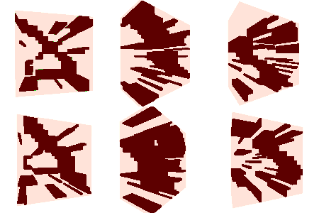
	ivec2 face = ivec2(UV / vec2(1.0/3.0, 1.0/2.0));
	// Make each face have similar UV
	vec2 adjusted_UV = mod(UV,vec2(1.0/3.0, 1.0/2.0)) * vec2(3.0, 2.0);

	// Z
	if (face.x == 0 && face.y == 0) {
		// No need to extrude if already on colored pixel
		vec4 color = texture(Texture, frameUV(adjusted_UV));
		if (color.w >= image_alpha_cull && keep_image) {
			ALBEDO = color.rgb;
			ALPHA = color.w;
		// Extrude
		} else {
			// From pixel cast ray from focal point to see if it collides with opaque pixel
			// If it collides, color the pixel with collided color
			imgPoint first_pixel = imgExtrude(adjusted_UV, model_ray.xy, false);
			ALBEDO = first_pixel.color.rgb;
			ALPHA = first_pixel.color.w;
			// Cap extruded end so it doesn't extrude infinitely
			// Does so by casting ray in opposite direction in order to find position of second collision
			vec3 point = vec3(UVtoXY(adjusted_UV),2.0);
			vec3 ray_intersection = PlaneLineIntersection(vec3(0.0), vec3(0.0,0.0,1.0), point, model_ray);
			vec2 uv_point = XYtoUV(ray_intersection.xy) + vec2(0.0,1.0);
			if (isInImg(uv_point)) {
				imgPoint second_pixel = imgExtrude(uv_point, -model_ray.xy, false);
				// If second raycast does not hit same texture on backface, then that pixel is clear
				if (model_ray.y <= 0.0 && second_pixel.uv.y < first_pixel.uv.y ) ALPHA = 0.0;
				else if (model_ray.y > 0.0 && second_pixel.uv.y > first_pixel.uv.y ) ALPHA = 0.0;
			}
		}
	}
	// -Z
	else if (face.x == 2 && face.y == 0) {
		// Back face has to be flipped in order to line up with front face
		vec4 color = texture(Texture, flippedFrameUV(adjusted_UV));
		if (color.w >= image_alpha_cull && keep_image) {
			ALBEDO = color.rgb;
			ALPHA = color.w;
		} else {
			imgPoint first_pixel = imgExtrude(adjusted_UV, vec2(-model_ray.x, model_ray.y), true);
			ALBEDO = first_pixel.color.rgb;
			ALPHA = first_pixel.color.w;

			vec3 point = vec3(UVtoXY(vec2(-adjusted_UV.x, adjusted_UV.y)),-2.0);
			vec3 ray_intersection = PlaneLineIntersection(vec3(0.0), vec3(0.0,0.0,1.0), point, model_ray);
			vec2 uv_point = XYtoUV(ray_intersection.xy) + vec2(1.0,1.0);
			if (isInImg(uv_point)) {
				imgPoint second_pixel = imgExtrude(uv_point, -model_ray.xy, false);
				if (model_ray.y <= 0.0 && second_pixel.uv.y < first_pixel.uv.y ) ALPHA = 0.0;
				else if (model_ray.y > 0.0 && second_pixel.uv.y > first_pixel.uv.y ) ALPHA = 0.0;
			}
		}
	}
	// X
	else if (face.x == 1 && face.y == 0) {
		// Convert pixel position on side of cube as if it is actually on same plane as texture on front of cube
		vec3 point = vec3(0.0, UVtoXY(adjusted_UV).yx);
		vec3 ray_intersection = PlaneLineIntersection(vec3(0.0), vec3(0.0,0.0,1.0), point, -model_ray);
		vec3 image_intersection = PlaneLineIntersection(vec3(0.0), vec3(1.0,0.0,0.0), ray_intersection, vec3(model_ray.xy, 0.0));
		vec2 new_uv = XYtoUV(image_intersection.xy) + vec2(0.5, 1.0);
		vec4 img_color = imgExtrude(new_uv, model_ray.xy, false).color;
		ALBEDO = img_color.rgb;
		ALPHA = img_color.w;
		// Find pixel position as if it is on front or back face and cast ray in opposite direction
		vec2 xy = UVtoXY(adjusted_UV);
		if (model_ray.z > 0.0) point = vec3(1.0, xy.y, -1.0 - xy.x);
		else point = vec3(1.0, xy.y, 1.0 - xy.x);
		ray_intersection = PlaneLineIntersection(vec3(0.0), vec3(0.0,0.0,1.0), point, model_ray);
		vec2 uv_point = XYtoUV(ray_intersection.xy) + vec2(0,1.0);
		if (isInImg(uv_point)) {
			// If ray collides with nothing then there can't be extrusion there
			vec4 img_color = imgExtrude(uv_point, -model_ray.xy, false).color;
			if (img_color.w == 0.0) ALPHA = 0.0;
		}
	}
	// -X
	else if (face.x == 0 && face.y == 1) {
		vec3 point = vec3(0.0, UVtoXY(adjusted_UV).yx);
		vec3 ray_intersection = PlaneLineIntersection(vec3(0.0), vec3(0.0,0.0,1.0), point, -model_ray);
		vec3 image_intersection = PlaneLineIntersection(vec3(0.0), vec3(-1.0,0.0,0.0), ray_intersection, vec3(model_ray.xy, 0.0));
		vec2 new_uv = XYtoUV(image_intersection.xy) + vec2(-0.5, 1.0);
		vec4 img_color = imgExtrude(new_uv, model_ray.xy, false).color;
		ALBEDO = img_color.rgb;
		ALPHA = img_color.w;

		vec2 xy = UVtoXY(adjusted_UV);
		if (model_ray.z > 0.0) point = vec3(-1.0, xy.y, -1.0 + xy.x);
		else point = vec3(-1.0, xy.y, 1.0 + xy.x);
		ray_intersection = PlaneLineIntersection(vec3(0.0), vec3(0.0,0.0,1.0), point, model_ray);
		vec2 uv_point = XYtoUV(ray_intersection.xy) + vec2(0.0,1.0);
		if (isInImg(uv_point)) {
			vec4 img_color = imgExtrude(uv_point, -model_ray.xy, false).color;
			if (img_color.w == 0.0) ALPHA = 0.0;
		}
	}
	// Y
	else if (face.x == 1 && face.y == 1) {
		vec2 rotated_UV = -UVtoXY(adjusted_UV);
		vec3 point = vec3(rotated_UV.x, 0.0, rotated_UV.y);
		vec3 ray_intersection = PlaneLineIntersection(vec3(0.0), vec3(0.0,0.0,1.0), point, -model_ray);
		vec3 image_intersection = PlaneLineIntersection(vec3(0.0), vec3(0.0,1.0,0.0), ray_intersection, vec3(model_ray.xy, 0.0));
		vec2 new_uv = XYtoUV(image_intersection.xy) + vec2(0.0,0.5);
		vec4 img_color = imgExtrude(new_uv, model_ray.xy, false).color;
		ALBEDO = img_color.rgb;
		ALPHA = img_color.w;

		vec2 xy = UVtoXY(vec2(-adjusted_UV.x, adjusted_UV.y));
		if (model_ray.z > 0.0) point = vec3(xy.x, 1.0, xy.y - 1.0);
		else point = vec3(xy.x, 1.0, xy.y + 1.0);
		ray_intersection = PlaneLineIntersection(vec3(0.0), vec3(0.0,0.0,1.0), point, model_ray);
		vec2 uv_point = XYtoUV(ray_intersection.xy) + vec2(1.0,1.0);
		if (isInImg(uv_point)) {
			vec4 img_color = imgExtrude(uv_point, -model_ray.xy, false).color;
			if (img_color.w == 0.0) ALPHA = 0.0;
		}
	}
	// -Y
	else if (face.x == 2 && face.y == 1) {
		vec2 XY = UVtoXY(adjusted_UV);
		vec3 point = vec3(XY.x, 0.0, XY.y);
		vec3 ray_intersection = PlaneLineIntersection(vec3(0.0), vec3(0.0,0.0,1.0), point, -model_ray);
		vec3 image_intersection = PlaneLineIntersection(vec3(0.0), vec3(0.0,-1.0,0.0), ray_intersection, vec3(model_ray.xy, 0.0));
		vec2 new_uv = XYtoUV(image_intersection.xy);
		new_uv += vec2(0.0, 1.5);
		vec4 img_color = imgExtrude(new_uv, model_ray.xy, false).color;
		ALBEDO = img_color.rgb;
		ALPHA = img_color.w;

		vec2 xy = UVtoXY(adjusted_UV);
		if (model_ray.z > 0.0) point = vec3(xy.x, -1.0, xy.y - 1.0);
		else point = vec3(xy.x, -1.0, xy.y + 1.0);
		ray_intersection = PlaneLineIntersection(vec3(0.0), vec3(0.0,0.0,1.0), point, model_ray);
		vec2 uv_point = XYtoUV(ray_intersection.xy) + vec2(0.0,1.0);
		if (isInImg(uv_point)) {
			vec4 img_color = imgExtrude(uv_point, -model_ray.xy, false).color;
			if (img_color.w == 0.0) ALPHA = 0.0;
		}
	}
}



@kidcolt, this is exactly what I’m looking for! I’m having an issue though, in Godot 4.2.stable I’m getting “Unknown identifier in expression: ‘gt’.” I do not see a ton of info about this error and if something changed from 4.1 to 4.2.
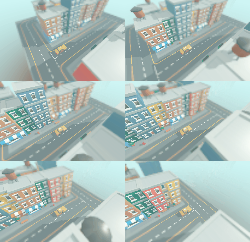
This looks great! i’m getting some weird lines in between though and when you look down the side it turns invisible, i’m guessing it something has changed between when this was made and the current version