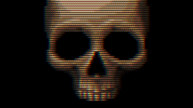
CRT with Luminance Preservation
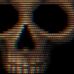
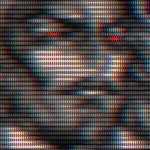
A fairly realistic CRT shader made with the intent of trying to get as close as possible to a real CRT on my 1080p monitor. It features screen curvature, scanlines, various phosphor arrangements, adjustable color misalignment, a sharpness slider, and more!
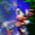
Screenshots usually don’t do the shader justice, so see the game ‘Dragon Dragon Fire Fire’ (playable in browser) for a good example of it working properly.
There’s a lot going on here, but one of the main underlying principals is luminance preservation, which means that an image passed into the shader will be roughly as bright as the result (and without any significant changes in saturation or contrast either). I do this by making the patterns most visible in the midtones but letting them disappear in highlights.
This all enables me to make artistic decisions about lighting and color for my project that wouldn’t be significantly different for players who turn off the CRT filter.
Note: I have managed to make several optimizations, but this shader still requires a rather high number of texture samples and calculations to get the effect I wanted, so it may impact performance. On the flip side, this shader is meant for retro games rendered at screen height / 4.5, so that might help make up for the cost.
Setup & Explanation:
This requires a texture much smaller than your screen’s resolution (otherwise scanlines get messed up), so the usual “hint_screen_texture” won’t be helpful here, and you should set the “tex” parameter as a ViewportTexture, and connect the texture’s viewport path to a SubViewport which has the camera and all 2D and 3D elements that you want filtered set as children of the SubViewport. Your material should be on a ColorRect that is a sibling of the SubViewport.
It might help to think of your SubViewport like a stage. Child nodes of the SubViewport are like props and actors on the stage. Your ViewportTexture is like a video feed of that stage (and for 3D elements, you need a camera for that video feed to work).
The size of your texture is controlled by your Subviewport. If you’re using a 1080 monitor (the most common) 240 works pretty well as a height. 240 is also the height of most PS1 games. If that resolution is too limiting, check out this alternate version of my shader which has no scanlines and works a lot better for higher resolutions.
Fixing Mouse Input:
In order to use the mouse with this effect, you’re going to need the script below or something similar. It will remap the mouse coordinates and pass input to nodes inside of the SubViewport.
# Put this script onto the ColorRect you're using to display the CRT effect
extends Control

# The SubViewport that will be rendered onto the CRT
@export var subviewport_node: SubViewport

# The default mouse filter for a ColorRect (stop) will stop this script from
# working, and it needs to be set to pass or ignore (both work).
# You can also just set this yourself and remove this function.
func _ready():
	mouse_filter = Control.MOUSE_FILTER_PASS

func _unhandled_input(event: InputEvent):

	if event is InputEventMouse:

		# Remap the coorinates of a mouse event to be at an apropriate point
		event.position -= position
		event.position *= Vector2(Vector2(subviewport_node.size) / size)

	subviewport_node.push_input(event)
Before doing a full setup, I’d recommend starting with a mostly blank scene with just a ColorRect with a CRT ShaderMaterial on it, and set the tex parameter as a static test image. You can use this to quickly experiment and see if the shader fits your project.
Quick Setup:
1: Create a ColorRect. Under layout, set Anchors Preset to “Full Rect”.
2: Create a new shader material for the ColorRect, set its shader to my CRT shader.
3: Create a SubViewport (I make it a sibling of the ColorRect). Almost everything else should be a child of the SubViewport.
4: After creating the SubViewport, go back to the material on the ColorRect. Right click the tex parameter and create new ViewportTexture. It will prompt you to select a SubViewport. There should be only the one you made earlier. Select that one.
5: Adjust the size of the ViewportTexture with the SubViewport. The height of this texture determines scanline count. 240 is usually a pretty safe choice.
V2: Reworked the texture sampling and managed to cut down on two samples without any significant loss in quality (I also found this by accident, lol), so hopefully the shader should be a bit more efficient.
Reworked the phosphor masks so that they are built into the shader and selected from a nice dropdown menu rather than having to swap out textures (this also saves another texture sample).
V3: Added a new mask pattern: “Soft Grille”.
Added a new feature “wobble” which is an attempt to capture a slight horizontal shaking that I’ve noticed in real CRTs. It is off by default.
Fixed the “Null” mask pattern which I had broken (whoops!).
Made several small revisions.
V4: Added seperate sliders for mask brightness and scanline brightness. Both can be reduced to perserve CRT details in bright areas at the cost of brightness.
Made several small revisions, fixed a rare bug.
Shader code
// CRT Shader by Harrison Allen
// V4

shader_type canvas_item;

/**
	The input texture that will have the CRT effect applied to it.
	Scanline count will be determined by this texture's height.
	You'll need to use a texture that's roughly screen height / 4.5
	(for instance 240 on a 1080 monitor or 480 on a 4k monitor)
	Else The scanlines won't properly resolve and you're get moiré patters.
	*/
uniform sampler2D tex: filter_linear;


/**
	Set the type of mask this CRT will have.
	Dots: emulates a typical PC CRT monitor.
	Grille: emulates an aperture grille. Good with higher curve values.
	Wide Grille: more suitable for 4k monitors.
	Soft Grille: very close to wide grille, but a little softer.
	Slot mask: this is the pattern found on most TVs, but it can clash with the
	scanlines unless the input texture resolution is halved.
	*/
uniform int mask_type : hint_enum(
	"Dots:1",
	"Aperture Grille:2",
	"Wide Grille:3",
	"Wide Soft Grille:4",
	"Slot Mask:5",
	"Null:0") = 1;

uniform float curve : hint_range(0.0, 0.5) = 0.0;

/**
	Controls how sharp the image is. Low values are fun with dithering, but a
	value of 0.5 will destroy high frequency details and render small text
	illegible. Use with care.
	*/
uniform float sharpness : hint_range(0.5, 1.0) = 0.6666666666666666666666666667;

/**
	Use to offset color channels from each other. I've personally observed this
	effect in real CRTs. It can go in either direction, and some CRTs are better
	aligned than others.
	I'd suggest offsetting this at least a little bit from the default value.
	Note that because of the typical RGB subpixel layout on on LCD, a very small
	positive value will actually align colors better (it depends on
	screen size), and -0.5 is just slightly more misaligned than 0.5, which is
	important if you want to be as misaligned as possible.
	*/
uniform float color_offset : hint_range(-0.5, 0.5) = 0.0;

/**
	Reduce to preserve phosphor mask details in highlights at the cost of
	overall brightness. This should usually be kept at or near 1
	*/
uniform float mask_brightness : hint_range(0, 1) = 1.0;

/**
	Reduce to preserve scanline details in highlights at the cost of
	overall brightness. This should usually be kept at or near 1
	*/
uniform float scanline_brightness : hint_range(0.5, 1.0) = 1.0;

/**
	Raising this value can help reduce Moiré patterns.
	A value of 1 will eliminate scanlines entirely.
	*/
uniform float min_scanline_thickness : hint_range(0.25, 1.0) = 0.5;

/**
	This should be the input texture's height divided by width.
	Only important if curve is used.
	For 16:9, this should be 0.5625.
	*/
uniform float aspect : hint_range(0.5, 1.0) = 0.75;

/**
	This controls slight horizontal shaking. This is set to 0 (off) by default.
	*/
uniform float wobble_strength : hint_range(0.0, 1.0) = 0.0;

varying flat float wobble;

void vertex()
{
	wobble = cos(TIME * TAU * 15.0) * wobble_strength / 8192.0;
}

vec2 warp(vec2 uv, float _aspect, float _curve)
{
	// Centralize coordinates
	uv -= 0.5;

	uv.x /= _aspect;

	// Squared distance from the middle
	float warping = dot(uv, uv) * _curve;

	// Compensate for shrinking
	warping -= _curve * 0.25;

	// Warp the coordinates
	uv /= 1.0 - warping;

	uv.x *= _aspect;

	// Decentralize the coordinates
	uv += 0.5;

	return uv;
}

vec3 linear_to_srgb(vec3 col)
{
	return mix(
		(pow(col, vec3(1.0 / 2.4)) * 1.055) - 0.055,
		col * 12.92,
		lessThan(col, vec3(0.0031318))
	);
}

vec3 srgb_to_linear(vec3 col)
{
	return mix(
		pow((col + 0.055) / 1.055, vec3(2.4)),
		col / 12.92,
		lessThan(col, vec3(0.04045))
	);
}


// Get scanlines from coordinates (returns in linear color)
vec3 scanlines(vec2 uv)
{
	// Set coordinates to match texture dimensions
	uv *= vec2(textureSize(tex, 0));

	// Vertical coordinate scanline samples
	int y = int(uv.y + 0.5) - 1;

	float x = floor(uv.x);

	// Horizontal coordinates for the texture samples
	float ax = x - 2.0;
	float bx = x - 1.0;
	float cx = x;
	float dx = x + 1.0;
	float ex = x + 2.0;

	// Sample the texture at various points
	vec3 upper_a = texelFetch(tex, ivec2(int(ax), y), 0).rgb;
	vec3 upper_b = texelFetch(tex, ivec2(int(bx), y), 0).rgb;
	vec3 upper_c = texelFetch(tex, ivec2(int(cx), y), 0).rgb;
	vec3 upper_d = texelFetch(tex, ivec2(int(dx), y), 0).rgb;
	vec3 upper_e = texelFetch(tex, ivec2(int(ex), y), 0).rgb;

	// Adjust the vertical coordinate for the lower scanline
	y += 1;

	// Sample the texture at various points
	vec3 lower_a = texelFetch(tex, ivec2(int(ax), y), 0).rgb;
	vec3 lower_b = texelFetch(tex, ivec2(int(bx), y), 0).rgb;
	vec3 lower_c = texelFetch(tex, ivec2(int(cx), y), 0).rgb;
	vec3 lower_d = texelFetch(tex, ivec2(int(dx), y), 0).rgb;
	vec3 lower_e = texelFetch(tex, ivec2(int(ex), y), 0).rgb;

	// Convert every sample to linear color
	upper_a = srgb_to_linear(upper_a);
	upper_b = srgb_to_linear(upper_b);
	upper_c = srgb_to_linear(upper_c);
	upper_d = srgb_to_linear(upper_d);
	upper_e = srgb_to_linear(upper_e);

	lower_a = srgb_to_linear(lower_a);
	lower_b = srgb_to_linear(lower_b);
	lower_c = srgb_to_linear(lower_c);
	lower_d = srgb_to_linear(lower_d);
	lower_e = srgb_to_linear(lower_e);

	// The x coordinates of electron beam offsets
	vec3 beam = vec3(uv.x - 0.5);
	beam.r -= color_offset;
	beam.b += color_offset;

	// Calculate weights
	vec3 weight_a = smoothstep(1, 0, (beam - ax) * sharpness);
	vec3 weight_b = smoothstep(1, 0, (beam - bx) * sharpness);
	vec3 weight_c = smoothstep(1, 0, abs(beam - cx) * sharpness);
	vec3 weight_d = smoothstep(1, 0, (dx - beam) * sharpness);
	vec3 weight_e = smoothstep(1, 0, (ex - beam) * sharpness);

	// This can be a fun place to raise each weight to some power

	// Mix samples into the upper scanline color
	vec3 upper_col = vec3(
		upper_a * weight_a +
		upper_b * weight_b +
		upper_c * weight_c +
		upper_d * weight_d +
		upper_e * weight_e
	);

	// Mix samples into the lower scanline color
	vec3 lower_col = vec3(
		lower_a * weight_a +
		lower_b * weight_b +
		lower_c * weight_c +
		lower_d * weight_d +
		lower_e * weight_e
	);

	vec3 weight_scaler = vec3(1.0) / (weight_a + weight_b + weight_c + weight_d + weight_e);

	// Normalize weight
	upper_col *= weight_scaler;
	lower_col *= weight_scaler;

	// Apply scanline brightness
	upper_col *= scanline_brightness;
	lower_col *= scanline_brightness;


	// Scanline size (and roughly the apperent brightness of this line)
	vec3 upper_thickness = mix(vec3(min_scanline_thickness), vec3(1.0), upper_col);
	vec3 lower_thickness = mix(vec3(min_scanline_thickness), vec3(1.0), lower_col);

	// Vertical sawtooth wave used to generate scanlines
	// Almost the same as fract(uv.y + 0.5), but prevents a rare visual bug
	float sawtooth = (uv.y + 0.5) - float(y);

	vec3 upper_line = vec3(sawtooth) / upper_thickness;
	upper_line = smoothstep(1.0, 0.0, upper_line);

	vec3 lower_line = vec3(1.0 - sawtooth) / lower_thickness;
	lower_line = smoothstep(1.0, 0.0, lower_line);

	// Correct line brightness below min_scanline_thickness
	upper_line *= upper_col / upper_thickness;
	lower_line *= lower_col / lower_thickness;

	// Combine the upper and lower scanlines
	return upper_line + lower_line;
}

vec4 generate_mask(vec2 fragcoord)
{
	switch (mask_type)
	{
		case 1: // Dots
			const vec3 pattern[] = {vec3(1,0,0), vec3(0,1,0), vec3(0,0,1), vec3(0,0,0)};

			ivec2 icoords = ivec2(fragcoord);

			return vec4(pattern[(icoords.y * 2 + icoords.x) % 4], 0.25);

		case 2: // Grille
			const vec3 pattern[] = {vec3(0,1,0), vec3(1,0,1)};

			return vec4(pattern[int(fragcoord.x) % 2], 0.5);

		case 3: // Wide grille
			const vec3 pattern[] = {
				vec3(1,0,0), vec3(0,1,0), vec3(0,0,1), vec3(0,0,0)};

			return vec4(pattern[int(fragcoord.x) % 4], 0.25);

		case 4: // Grille wide soft
			const vec3 pattern[] = {
				vec3(1.0,0.125,0.0),
				vec3(0.125,1.0,0.125),
				vec3(0.0,0.125,1.0),
				vec3(0.125,0.0,0.125)};

			return vec4(pattern[int(fragcoord.x) % 4], 0.3125);

		case 5: // Slotmask
			const vec3 pattern[] = {
				vec3(1,0,1), vec3(0,1,0), vec3(1,0,1), vec3(0,1,0),
				vec3(0,0,1), vec3(0,1,0), vec3(1,0,0), vec3(0,0,0),
				vec3(1,0,1), vec3(0,1,0), vec3(1,0,1), vec3(0,1,0),
				vec3(1,0,0), vec3(0,0,0), vec3(0,0,1), vec3(0,1,0)
			};

			ivec2 icoords = ivec2(fragcoord) % 4;

			return vec4(pattern[icoords.y * 4 + icoords.x], 0.375);

		default:
			return vec4(0.5);
	}
}

// Add phosphor mask/grill
vec3 mask(vec3 linear_color, vec2 fragcoord)
{
	// Get the pattern for the mask. Mask.w equals avg. brightness of the mask
	vec4 mask = generate_mask(fragcoord);

	// Dim the color if brightness is reduced to preserve mask details
	linear_color *= mix(mask.w, 1.0, mask_brightness);

	// How bright the color needs to be to maintain 100% brightness while masked
	vec3 target_color = linear_color / mask.w;

	// Target color limited to the 0 to 1 range.
	vec3 primary_col = clamp(target_color, 0.0, 1.0);

	// This calculates how bright the secondary subpixels will need to be
	vec3 highlights = target_color - primary_col;
	highlights /= 1.0 / mask.w - 1.0;

	primary_col *= mask.rgb;

	// Add the secondary subpixels
	primary_col += highlights * (1.0 - mask.rgb);

	return primary_col;
}

void fragment()
{
	// Warp UV coordinates
	vec2 warped_coords = warp(UV, aspect, curve);

	// Add wobble
	warped_coords.x += wobble;

	// Sample the scanlines
	vec3 col = scanlines(warped_coords);

	// Apply phosphor mask
	col = mask(col, FRAGCOORD.xy);

	// Convert back to srgb
	col = linear_to_srgb(col);

	COLOR.rgb = col;
}
Live Preview

Hey how does this actually get set up?
Ah, sorry for not explaining. I use a subviewport to render a scene as a viewport texture, which gets passed into the shader material as the “tex” parameter. The crt shader material is put onto a color rect and that’ll make it show up on screen. Here’s the documentation on subviewports: https://docs.godotengine.org/en/stable/classes/class_subviewport.html#class-subviewport
Make sure to create a mask texture, though. Otherwise this won’t work properly.
Can you do some sort of walkthrough on this?
I can’t really seem to figure out how to actually get this working. I apologize, subviewports are not really my forte. And it seems difficult trying to find documentation about it
Start out with a scene that’s just two things at first: a ColorRect, and a SubViewport.
Next, setup your ColorRect to have a ShaderMaterial with the CRT shader on it.
Right click the “tex” parameter and create a new ViewportTexture (top of the list).
Link that texture to the SubViewport. Add a camera, objects, and everything else in your scene as a child of the SubViewport.
The main camera that is a child of the SubViewport should now render to the ViewportTexture. And you should be able to adjust the texture size in the SubViewport’s settings.
I hope that helps!
I’ve also updated the shader code over the past week. It’s a little cleaner, has fewer texture samples, and now the mask type can be selected from a simple dropdown instead of having to recreate textures, making it a lot more user friendly.
its my first time using shaders and that explanation helped a lot to start , thanks
hey, i’m trying to apply this texture to a mesh as a subviewport texture, to make it look like a TV with your shader effect. it seems that i can’t manage to because the subviewport i need to use as my texture is itself rendering a subviewport because of this limitation. is there any way around this? 😩
So, if I understand rightly, are you trying to put this shader onto a 3D object in the game world?
Unfortunately I think that part of the problem here is that this is a canvas item shader (or a 2D shader) but what you’d need for a 3D mesh is a spatial shader, and my shader wouldn’t be suitable for a 3D object anyway.
ahhhh, it’s more like, i can get it working in 2D, but i’m trying to use the resulting control node as the child of a subviewport that i can apply as a texture to a 3D object because it should just display the 2D control node as-is. but i’m wondering if the chained subviewports is making that an issue.
Oh, I think I do get it now. I do not know, I’ve never actually done anything with chained Subviewports, though, so I don’t know how to fix that. Sorry!
can I use this for my commercial game ?
Yes! 🙂 I’ve put this under a public domain license, so you’re free to make a commercial product with it (and, honestly, that’s what I want, because I think more retro games need a CRT filter). You can see the license just under the shader’s tags on this page for details.
Also, I’ve still been actively working on improving this shader, so it might be worth it to check back occasionally to see if I’ve updated it.
this looks incredible, it’s people like you that keep the world turning dude!
I’m having an issue where the CRT mask extends far past the intended area. It even goes out into the inspector. I’m using the linux version of godot, if that helps?
It’s most apparent with the “aperture grille” mask type, but happens with all choices.
Wow, that’s pretty wild. I didn’t even know that was possible. I don’t know how to fix that. Sounds like it’s a bug with the editor.
This is great! I was wondering if you have plans for a version that’s compatible with Godot 4.3? I happen to be using that version and it didn’t work as-is. However, I’ve made the appropriate changes to get it working with that version now.
Here’s the shader code in case you wanted to expand on it, or for other 4.3 users:
// CRT Shader by Harrison Allen // V4 (Godot 4.3-safe version) shader_type canvas_item; // --------- Uniforms --------- uniform sampler2D tex; // assign a ViewportTexture (from your SubViewport) uniform int mask_type = 0; // 0=Dots, 1=Aperture Grille, 2=Wide Grille, 3=Wide Soft Grille, 4=Slot Mask, 5=Null uniform float curve = 0.5; uniform float sharpness = 0.6666667; uniform float color_offset = 0.0; uniform float aspect = 0.75; // height/width of input (e.g., 0.5625 for 16:9) uniform float min_scanline_thickness = 0.5; uniform float wobble_strength = 0.0; // NEW: separate brightness controls (like V4) uniform float mask_brightness = 1.0; // 0..1 (lower to preserve mask detail in brights) uniform float scanline_brightness = 1.0; // 0.5..1 (lower to preserve scanline detail in brights) varying float wobble; void vertex() { // use explicit 2*PI to avoid TAU issues wobble = cos(TIME * 6.283185307179586 * 15.0) * wobble_strength / 4000.0; } vec2 warp(vec2 uv, float _aspect, float _curve) { uv -= 0.5; uv.x /= _aspect; float warping = dot(uv, uv) * _curve; warping -= _curve * 0.25; uv /= (1.0 - warping); uv.x *= _aspect; uv += 0.5; return uv; } vec3 linear_to_srgb(vec3 col) { bvec3 cut = lessThan(col, vec3(0.0031318)); vec3 a = (pow(col, vec3(1.0 / 2.4)) * 1.055) - 0.055; vec3 b = col * 12.92; return mix(a, b, cut); } vec3 srgb_to_linear(vec3 col) { bvec3 cut = lessThan(col, vec3(0.04045)); vec3 a = pow((col + 0.055) / 1.055, vec3(2.4)); vec3 b = col / 12.92; return mix(a, b, cut); } // Get scanlines from coordinates (returns in linear color) vec3 scanlines(vec2 uv) { uv *= vec2(textureSize(tex, 0)); int y = int(floor(uv.y - 0.5)); float x = floor(uv.x); float ax = x - 2.0; float bx = x - 1.0; float cx = x; float dx = x + 1.0; float ex = x + 2.0; vec3 upper_a = texelFetch(tex, ivec2(int(ax), y), 0).rgb; vec3 upper_b = texelFetch(tex, ivec2(int(bx), y), 0).rgb; vec3 upper_c = texelFetch(tex, ivec2(int(cx), y), 0).rgb; vec3 upper_d = texelFetch(tex, ivec2(int(dx), y), 0).rgb; vec3 upper_e = texelFetch(tex, ivec2(int(ex), y), 0).rgb; y += 1; vec3 lower_a = texelFetch(tex, ivec2(int(ax), y), 0).rgb; vec3 lower_b = texelFetch(tex, ivec2(int(bx), y), 0).rgb; vec3 lower_c = texelFetch(tex, ivec2(int(cx), y), 0).rgb; vec3 lower_d = texelFetch(tex, ivec2(int(dx), y), 0).rgb; vec3 lower_e = texelFetch(tex, ivec2(int(ex), y), 0).rgb; upper_a = srgb_to_linear(upper_a); upper_b = srgb_to_linear(upper_b); upper_c = srgb_to_linear(upper_c); upper_d = srgb_to_linear(upper_d); upper_e = srgb_to_linear(upper_e); lower_a = srgb_to_linear(lower_a); lower_b = srgb_to_linear(lower_b); lower_c = srgb_to_linear(lower_c); lower_d = srgb_to_linear(lower_d); lower_e = srgb_to_linear(lower_e); vec3 beam = vec3(uv.x - 0.5); beam.r -= color_offset; beam.b += color_offset; vec3 weight_a = smoothstep(1.0, 0.0, (beam - ax) * sharpness); vec3 weight_b = smoothstep(1.0, 0.0, (beam - bx) * sharpness); vec3 weight_c = smoothstep(1.0, 0.0, abs(beam - cx) * sharpness); vec3 weight_d = smoothstep(1.0, 0.0, (dx - beam) * sharpness); vec3 weight_e = smoothstep(1.0, 0.0, (ex - beam) * sharpness); vec3 upper_col = upper_a * weight_a + upper_b * weight_b + upper_c * weight_c + upper_d * weight_d + upper_e * weight_e; vec3 lower_col = lower_a * weight_a + lower_b * weight_b + lower_c * weight_c + lower_d * weight_d + lower_e * weight_e; vec3 weight_scaler = vec3(1.0) / (weight_a + weight_b + weight_c + weight_d + weight_e); upper_col *= weight_scaler; lower_col *= weight_scaler; // NEW: apply scanline brightness BEFORE computing thickness/shapes upper_col *= scanline_brightness; lower_col *= scanline_brightness; vec3 upper_thickness = mix(vec3(min_scanline_thickness), vec3(1.0), upper_col); vec3 lower_thickness = mix(vec3(min_scanline_thickness), vec3(1.0), lower_col); float sawtooth = fract(uv.y + 0.5); vec3 upper_line = vec3(sawtooth) / upper_thickness; upper_line = smoothstep(1.0, 0.0, upper_line); vec3 lower_line = vec3(1.0 - sawtooth) / lower_thickness; lower_line = smoothstep(1.0, 0.0, lower_line); upper_line *= upper_col / upper_thickness; lower_line *= lower_col / lower_thickness; vec3 combined = upper_line + lower_line; // Keep the darker fallback for very thin lines vec3 dark_upper = smoothstep(min_scanline_thickness, 0.0, vec3(sawtooth)) * upper_col; vec3 dark_lower = smoothstep(min_scanline_thickness, 0.0, vec3(1.0 - sawtooth)) * lower_col; vec3 dark_combined = dark_upper + dark_lower; // Use scanline_brightness already applied; return the shaped result // (No extra global "brightness" mix anymore) // Slight bias toward shaped lines: return mix(dark_combined, combined, 0.9); } // ----- Small helpers (no arrays/ternaries) ----- vec3 _pick4(int idx, vec3 a, vec3 b, vec3 c, vec3 d) { if (idx == 0) return a; if (idx == 1) return b; if (idx == 2) return c; return d; } vec3 _slot_color(int idx) { // 16-item pattern spelled out explicitly if (idx == 0) return vec3(1,0,1); if (idx == 1) return vec3(0,1,0); if (idx == 2) return vec3(1,0,1); if (idx == 3) return vec3(0,1,0); if (idx == 4) return vec3(0,0,1); if (idx == 5) return vec3(0,1,0); if (idx == 6) return vec3(1,0,0); if (idx == 7) return vec3(0,0,0); if (idx == 8) return vec3(1,0,1); if (idx == 9) return vec3(0,1,0); if (idx == 10) return vec3(1,0,1); if (idx == 11) return vec3(0,1,0); if (idx == 12) return vec3(1,0,0); if (idx == 13) return vec3(0,0,0); if (idx == 14) return vec3(0,0,1); return vec3(0,1,0); } vec4 generate_mask(vec2 fragcoord) { int mx = mask_type; if (mx == 0) { // Dots ivec2 icoords = ivec2(floor(fragcoord)); int idx = (icoords.y * 2 + icoords.x) % 4; vec3 c = _pick4(idx, vec3(1,0,0), vec3(0,1,0), vec3(0,0,1), vec3(0,0,0)); return vec4(c, 0.25); } else if (mx == 1) { // Aperture Grille int idx = int(floor(fragcoord.x)) % 2; vec3 c = vec3(0.0); if (idx == 0) c = vec3(0,1,0); else c = vec3(1,0,1); return vec4(c, 0.5); } else if (mx == 2) { // Wide Grille int idx = int(floor(fragcoord.x)) % 4; vec3 c = _pick4(idx, vec3(1,0,0), vec3(0,1,0), vec3(0,0,1), vec3(0,0,0)); return vec4(c, 0.25); } else if (mx == 3) { // Wide Soft Grille int idx = int(floor(fragcoord.x)) % 4; vec3 c = _pick4(idx, vec3(1.0, 0.125, 0.0), vec3(0.125, 1.0, 0.125), vec3(0.0, 0.125, 1.0), vec3(0.125, 0.0, 0.125) ); return vec4(c, 0.3125); } else if (mx == 4) { // Slot Mask ivec2 ico = ivec2(floor(fragcoord)); int ix = ico.x % 4; int iy = ico.y % 4; int idx = iy * 4 + ix; vec3 c = _slot_color(idx); return vec4(c, 0.375); } else { // Null return vec4(0.5); } } // Add phosphor mask/grille (uses mask_brightness like V4) vec3 mask(vec3 linear_color, vec2 fragcoord) { vec4 m = generate_mask(fragcoord); // Dim base to preserve mask detail in highlights (1.0 = no dimming) float dim = mix(m.w, 1.0, mask_brightness); linear_color *= dim; // Compute primary + highlights same as V4 vec3 target_color = linear_color / m.w; vec3 primary_col = clamp(target_color, 0.0, 1.0); vec3 highlights = target_color - primary_col; highlights /= (1.0 / m.w - 1.0); primary_col *= m.rgb; primary_col += highlights * (1.0 - m.rgb); return primary_col; } void fragment() { vec2 warped_coords = warp(UV, aspect, curve * 0.5); warped_coords.x += wobble; vec3 col = scanlines(warped_coords); col = mask(col, FRAGCOORD.xy); col = linear_to_srgb(col); COLOR.rgb = col; }Wow! No plans to port it myself, but thanks for sharing this so that others might benefit. 🙂 You seem to understand the code pretty well. 👍
The only thing I’d point out is that because of the slight modifications you’ve made to the end of the scanline function (with the 0.9 mix) full luminance is no longer preserved even if scanline brightness is at mask.
I was unhappy with the extra calculations for dim scanlines in versions 1 to 3, especially since I usually keep the brightness at max, and I realized that simply reducing the brightness before calculating the scanlines has roughly the same effect with fewer calculations and less code (there is a very slight difference between the two, but I compared them closely and felt that neither felt particularly better or worse than the other). I see you’ve included some of the new functionality of V4, but I’d suggest just keeping mostly the same V4 scanline code and setting your scanline brightness somewhere in the 0.90s. Although if you are fond of the old slightly different shapes, you could just go mostly back to the V3 version by removing the two new early scanline brightness multiplications and replace the 0.9 with scanline_brightness.
Also, I apologize for updating this seemingly in the middle of your conversion without documenting my changes particularly well, that must make things a bit confusing.
BTW, I’m curious about your reworking of the mask generation. Are these changes important for the Godot 4.3 conversion, or are these optimizations? I ask because I’m not particularly well versed in what techniques are better than others and I’m interested in knowing more when I can.
And, again, thanks you for sharing this. 👍
Thanks for pointing that out. I may try making that change. I also wanted to attempt bringing in some ideas I’ve seen other CRT shaders do like a screen warp.
I don’t often make shaders but like to tweak other peoples. I was working on altering a CRT shader I found previously but yours is much better all around, so I’m going to try and merge some of the ideas and try to build my own. With the previous one I was working on, I had added an RGB split optics compensation effect. It’s not realistic to how CRT displays work but the effect is pretty cool, so I’ll try and integrate it as a slider option.
Now that you pointed this out and I’ve researched further, it seems the changes I made weren’t so much to do with the godot version but rather to make it compile in compatibility mode which was giving me issues with hints, arrays, and ternary operators. So changing that aspect of the shader made things work. My mistake.
I’m very interested to see what changes you implement, so if you end up posting it, please do send me a link to it.
I’ve still got a few ideas that I haven’t quite gotten in here. One thing I’d really like to do is to make it properly feel like you’re looking through a thick layer of glass with some extra bloom, and possibly a subtle reflection (if I go this far I’ll probably post is as a separate shader rather than updating this one).
Oh yeah, that would be really cool. I’ll keep following what you’re doing as I’m not sure how you’d go about accomplishing that glass look but it sounds like it could be great.
I’ll reply again once I have something working and you can feel free to pull any additions I come up with into your own shader. What I’m doing might be a little different anyways as I’m trying to keep everything lightweight to work in compatibility mode (I’m trying to develop a retro point-and-click game).
Here’s what I came up with. It might be a bit overkill but there may be some concepts in there that you want to pull out and use for your own shader.
[…] had an adventure of trying to implement the CRT shader that went semi-viral on r/Godot. Despite successfully implementing it, which required some changes […]
Dude, I need help…
in the shader when I click tex and “new viewport” godot sends me this warning
“Can’t create a ViewportTexture on this resource because it’s not set as local to scene.
Please switch on the ‘local to scene’ property on it (and all resources containing it up to a node).”
I am on godot 4.4
You’ll need to make the material local to the scene. With your material selected, click on the “Resource” section, which is right under the “Shader Parameters” section. check the box labeled “Local to Scene” and think that might do it.
It’d be cool if this could be reconfigured to take advantage of the new BackBufferCopy node.
Oh, nevermind it actually works out-of-the-box with BackBufferCopy; just have to add hint_screen_texture before the filter_linear on tex
Hi im having trouble getting my mouse inputs to work with this. so far i have tried enabling object picking on the subviewport, ignoring mouse on the colorrect, and even putting everything inside a subviewportcontainer
i can get input to work if i put it in a subviewportcontainer and use push_input to the subviewport, but inside a subviewportcontainer the shader doesnt show. might be an issue with my computer not sure yet though
Sorry for the late response. As of yet, I have not actually tried implementing this at the same time as a mouse menu, so unfortunately I don’t have any experience with that particular issue.
Okay, I have finally gotten around to developing a fix for this issue (better late than never). You need a small script on the ColorRect to pass inputs to the SubViewport.
I’ve added the script to the description and it should be pretty easy to add to the setup.
(Sorry for being so late with this lol)
I have a 3D game, where I have a monitor set up. It is a 3D scene, using a subviewport that contains only the control nodes for the monitor scene. I display this, by having a QuadMesh and having it’s Albedo Texture be the Viewport Texture of said viewport.
I am not sure how to set up your shader in this scenario. I tried adding another viewport, I tried adding the ColorRect inside the control elements of my first viewport. Nothing ends up looking as I expect and I keep getting the moire pattern. I would appreciate any help! Thanks 🙂
@PS:
When I set it up as follows:
SubViewport1 (the computer ui)
QuadMesh (renders the above subviewport)
Camera
SubViewPort2
I can kind of overlay it, but it doesn’t actually apply the shader to the elements, but acts as a sort of overlay – and it renders incorrectly, with lots of vertical lines.
If you want to use this for a 3D scene, then perhaps you could convert this from a canvas item shader to a spatial shader. It would take a little bit of work, but I think it might be worth it for the optimal result.
I’m not sure about everything you’d have to do right now, but I can at least think of a few steps that might work:
Change shader_type from canvas_item to spatial.
add the line “render_mode unshaded;” near the top just under shader_type.
Remove the line that warps the texture coords and its associated function (instead you might do any warping with the geometry of the mesh).
Change COLOR.rgb to ALBEDO near the end.
Remove the linear/rgb conversions and the two related functions (the engine usually handles the conversion while in 3D)
Possibly add source_color as a tag on the tex parameter (not sure right now).
And that’s all that I can remember right now.
Note that this shader isn’t really made for a 3D scene. The phosphor pattern works on the subpixels of the user’s LCD’s, and the pattern will be locked to that if you move it around on camera (but this won’t be an issue for a static screen). If you are using this in a non-static setup, I’d suggest also just removing the entire mask function and the line that calls it, relying instead solely on the scanlines.
[…] credit to crt shader :CRT with Luminance Preservation – Godot Shaders […]